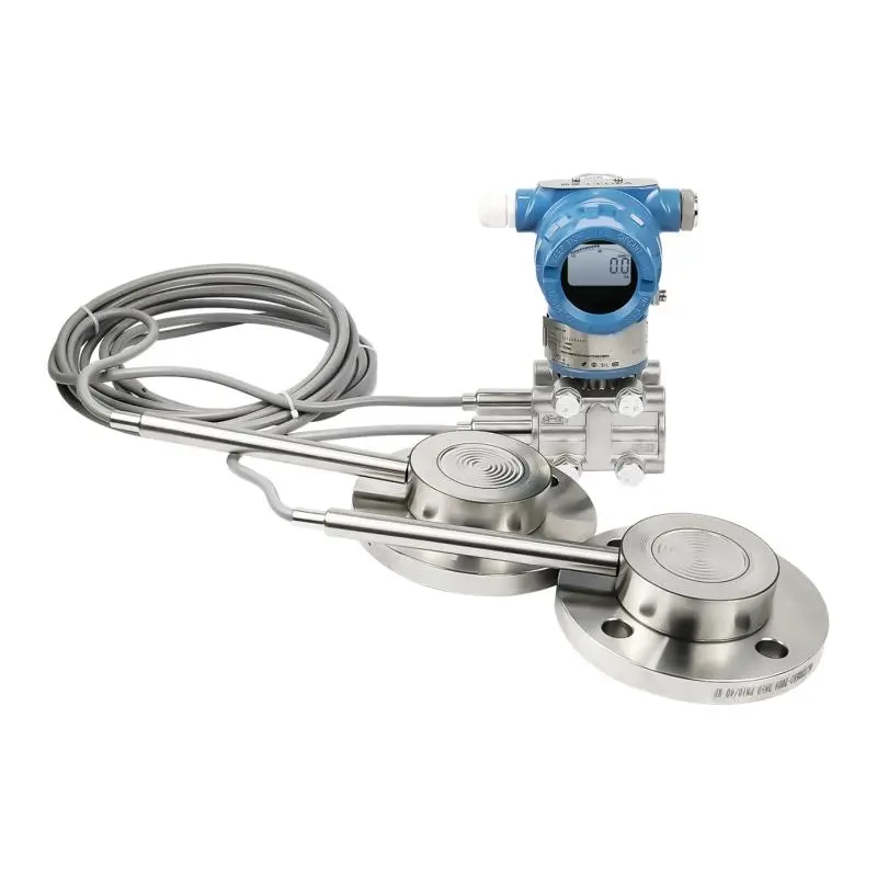
Dual Flange Differential Pressure Transmitter
A Dual Flange Differential Pressure Level Transmitter is an industrial instrument specially designed for continuous level measurement in closed vessels, pressurized storage tanks, reactors, and other complex process containers. It is typically composed of a differential pressure transmitter body, upper and lower flange diaphragm seal assemblies, dual-side capillary remote seal systems, and internal fill fluid. It can provide stable and reliable level monitoring and remote output under demanding conditions such as high temperature, pressure, corrosion, viscosity, and crystallizing media.
Compared with a conventional differential pressure transmitter, the dual flange structure is not simply a matter of connecting two pressure tapping points to the transmitter. Instead, it uses upper and lower diaphragm seal flanges to isolate the process medium from the sensitive internal elements of the instrument, and then transmits pressure to the differential pressure sensor through capillaries and fill fluid. This design effectively helps prevent problems such as blocked impulse lines, leakage, liquid accumulation, and direct heat transfer, making it better suited for long-term continuous industrial operation.
For level measurement applications involving vapor pressure at the top of the vessel, steam space, nitrogen blanketing, corrosive media, or sticky products, a dual flange differential pressure level transmitter is usually one of the more reliable and mature solutions.
- Pressure Type: Gauge Pressure, Differential Pressure, Level
- Pressure Range:
- -1 bar to 30 bar, 0~300mH2O
- Accuracy: ±0.075%, ±0.2%
- Output Signal: 4–20 mA / HART
- Process Connection: DN20 / DN25 / DN40 / DN50 / DN65 / DN80 / DN100 / DN150 (customized available)
- Diaphragm Material: SS316L, HC-276, Tantalum, Gold-plated
- Capillary length: 1-10 meters (length can be customized upon request)
- Power Supply: 12–36 VDC
- Protection Rating: IP65 / IP67
- OEM Service: Available. The transmitter can be supplied with your company name and logo on the nameplate.
- Packaging: Individual carton box with protective foam.
- Weight: Approx. 7 kg per unit.
- Port of Shipment: Shanghai or Ningbo Port, China.
- Delivery Time: 3-7 working days.
- Transportation: Air freight, sea freight, or express delivery.
- Documentation: Certificate of Conformity (COC); Inspection / Test Report; Packing List; Commercial Invoice
Accessories
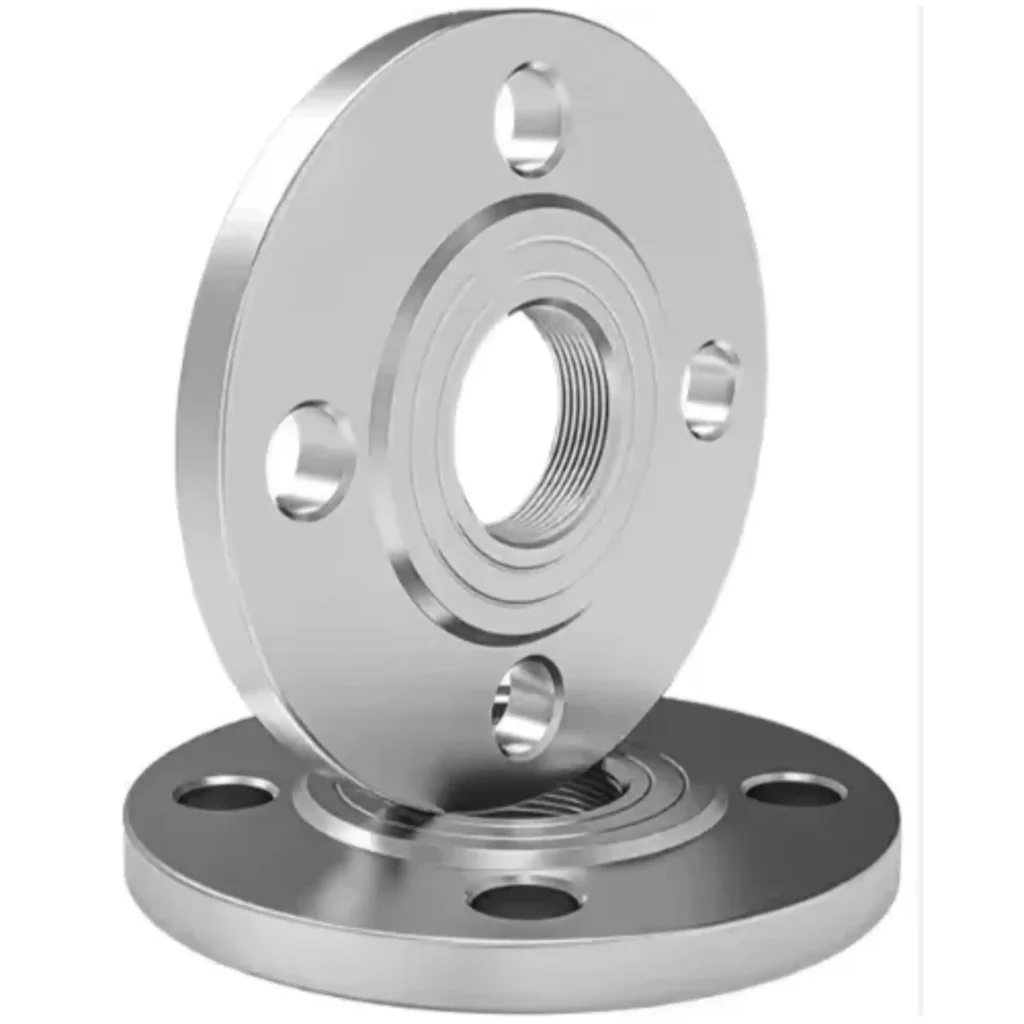

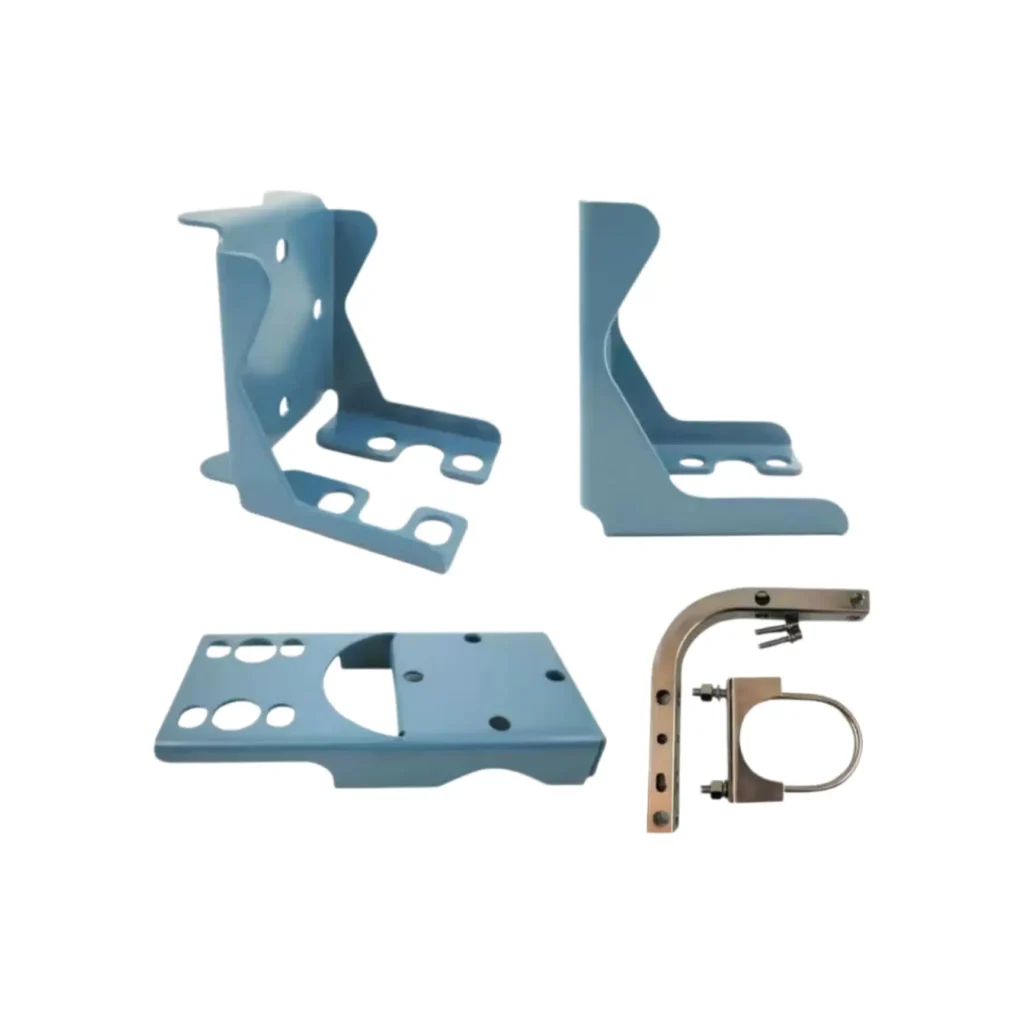
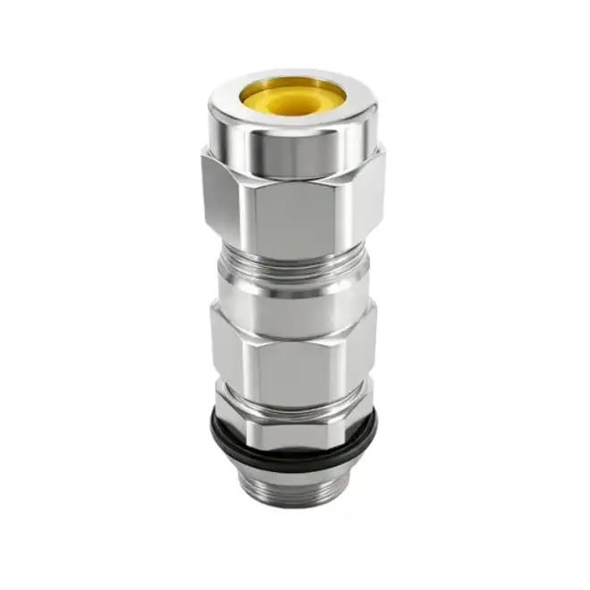
Table of Contents
Basic Introduction to Dual Flange Differential Pressure Transmitter
1. What Is a Dual Flange Differential Pressure Transmitter?
A dual flange differential pressure level transmitter is essentially a diaphragm seal differential pressure transmitter used for level measurement.
“Dual flange” means that the instrument is equipped with flange diaphragm seal assemblies on both the high-pressure side and the low-pressure side. “Differential pressure level” means that it does not measure liquid level directly as a height, but instead measures the pressure difference between two points in the vessel and then converts that differential pressure into liquid level.
In many applications, especially in closed tanks and pressurized vessels, level measurement cannot be accurately achieved by simply installing a pressure transmitter at the bottom. This is because the bottom pressure includes not only the hydrostatic pressure of the liquid column, but also the vapor pressure at the top of the vessel. If the top pressure is not compensated or eliminated, the measured value will not represent true liquid level alone.
A dual flange differential pressure level transmitter solves this problem by sensing the bottom liquid pressure and the top vapor pressure separately through two process connections, then calculating the difference inside the transmitter to obtain the true differential pressure corresponding to the liquid level.
Compared with an ordinary differential pressure transmitter, it is more suitable for high-temperature, corrosive, viscous, crystallizing, and clogging media.
Compared with a single flange differential pressure level transmitter, it is more suitable for closed tanks, pressurized vessels, and applications with obvious fluctuations in top pressure.
Compared with conventional direct-mount level measurement solutions, its structure is more complex, but under demanding service conditions it is usually more stable and more durable.
2. Structure and Diagram of a dual flange differential pressure level transmitter
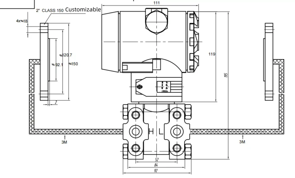
A dual flange differential pressure level transmitter typically consists of the following components:
Differential Pressure Transmitter Body
This is the core signal processing unit of the instrument. It receives the pressure signals from both sides and converts them into standard outputs such as 4–20 mA and HART. The common housing style is similar to a 3051-type industrial transmitter and is suitable for long-term field service.
High-Pressure Side Flange Diaphragm Seal Assembly
Installed at the lower part of the vessel or the lower process connection, it senses the combined pressure of the liquid column and top vapor pressure.
Low-Pressure Side Flange Diaphragm Seal Assembly
Installed at the upper part of the vessel or in the vapor space connection, it senses the top vapor pressure. This pressure is canceled out in the differential pressure calculation.
Dual-Side Capillary Remote Seal System
The pressures from both the high-pressure side and low-pressure side are transmitted to the transmitter body through fill fluid inside the capillaries. This is why dual flange products place particular emphasis on capillary routing, capillary length, and consistency of thermal conditions.
Internal Fill Fluid
The diaphragm seal system is filled with special fill fluid for stable pressure transmission. The fill fluid selection is closely related to temperature range, response speed, and thermal drift performance.
Flanged Process Connections
These are used to mount the upper and lower diaphragm seal assemblies onto the corresponding vessel connections. Flange size, standard, diameter, and pressure class can be customized according to project requirements.
Mounting Bracket
Used to secure the transmitter body for more stable installation and easier wiring.
Display Head and Electrical Connection
Some models can be equipped with an LCD display for direct on-site viewing of level, percentage, current, or differential pressure values. Electrical connection options usually include M20×1.5 and 1/2-14 NPT.
3. Inline Pressure Transmitters Working Principle
- Hydrostatic pressure from the liquid column
- Vapor pressure at the top of the vessel
- The high-pressure side flange is installed at the lower part of the vessel to sense the total bottom pressure
- The low-pressure side flange is installed at the upper part of the vessel to sense the top vapor pressure
- Medium density
- Operating temperature
- Vessel pressure
- High-pressure and low-pressure side installation positions
- Capillary length and structure
4. Applications of Dual Flange Differential Pressure Transmitter
A dual flange differential pressure level transmitter is commonly used in the following applications:
Closed Tank Level Measurement
For tanks with vapor pressure at the top, the dual flange structure can effectively eliminate the influence of top pressure fluctuations on the level output.
Pressurized Vessel Level Measurement
For vessels with nitrogen blanketing, steam protection, or pressure control, the dual flange solution is a more common industrial choice.
High-Temperature Reactor Level Measurement
Hot media should not act directly on the transmitter body. The capillary remote seal structure provides effective thermal isolation.
Steam-Covered Vessel Level Measurement
When there are changes in temperature and pressure in the vapor space, the dual flange structure provides more stable level compensation.
Viscous Media Level Measurement
For slurry, resin, syrup, sludge, and similar media, ordinary impulse lines are prone to clogging, while diaphragm seal structures are more suitable.
Crystallizing Media Level Measurement
When media tend to accumulate, deposit, or crystallize in impulse lines, the dual flange design is usually more reliable.
Corrosive Media Level Measurement
With properly selected diaphragm materials such as 316L, Hastelloy, or tantalum, it can adapt to different corrosive applications.
Volatile Media Level Measurement
When the vapor space at the top is unstable, the dual flange structure can more effectively deal with vapor pressure influence.
5. Why Many Applications Require a Dual Flange Structure
In many projects, a dual flange solution is not just a more advanced option, but a necessary one.
This is because ordinary level measurement methods often cannot operate reliably for the long term when the following conditions exist:
- Pressure at the top of the vessel
- Media on both the high-pressure side and low-pressure side are not suitable for direct impulse piping
- Ordinary impulse lines are prone to clogging, crystallization, liquid accumulation, or leakage
- Medium temperature is too high for direct mounting of the transmitter at the connection
- The medium is highly corrosive and requires isolation measurement
- The medium is viscous or sticky, making ordinary pressure tapping methods maintenance-intensive
- The project requires long-term stable level measurement and easy integration with automation systems
For these reasons, in level measurement for closed vessels and complex process containers, a dual flange differential pressure level transmitter is a very mature and reliable type of solution.
Dual Flange Differential Pressure Level Transmitter Product Technology
1. Technical Specifications of Dual Flange Differential Pressure Level Transmitter
| SIY3051C Diaphragm Seal Differential Pressure Level Transmitter Selection Table | ||||
| 10 | Transmitter type | |||
| D | Differential pressure transmitter | |||
| G | Gauge pressure transmitter | |||
| A | Absolute pressure transmitter | |||
| 20 | Accuracy | |||
| -H | Basic error ±0.075% | |||
| -N | Basic Error ±0.2% | |||
| 30 | Pressure Range | |||
| 3051CD Differential pressure | ||||
| 3 | -6kPa~6kPa(-60mbar~60mbar) | |||
| 4 | -40kPa~40kPa(-400mbar~400mbar) | |||
| 5 | -250kPa~250kPa(-2.5bar~2.5bar) | |||
| 6 | -1MPa~1MPa(-10bar~10bar) | |||
| 7 | -3MPa~3MPa(-30bar~30bar) | |||
| 9 | Other agreed pressure ranges | |||
| 3051CG Gauge pressure | ||||
| 3 | -6kPa~6kPa(-60mbar~60mbar) | |||
| 4 | -40kPa~40kPa(-400mbar~400mbar) | |||
| 5 | -100kPa~250kPa(-1bar~2.5bar) | |||
| 6 | -0.1MPa~1MPa(-1bar~10bar) | |||
| 7 | -0.1MPa~3MPa(-1bar~30bar) | |||
| 8 | -0.1MPa~10MPa(-1bar~100bar) | |||
| 9 | -0.1MPa~21MPa(-1bar~210bar) | |||
| 10 | -0.1MPa~40MPa(-1bar~400bar) | |||
| 3051CA Absolute pressure | ||||
| 4 | 0~40kPa(0~0.4bar) | |||
| 5 | 0~250kPa(0~2.5bar) | |||
| 6 | 0~3MPa(0~30bar) | |||
| 9 | Other agreed pressure ranges | |||
| Note: 3051CD static pressure: 16 MPa / 25 MPa / 40 MPa | ||||
| 40 | Communication Protocol | |||
| H | 4–20 mA + HART5/HART6/HART7 communication protocol | |||
| M | RS485 Modbus communication protocol | |||
| 50 | Diaphragm material | |||
| 2 | 316 stainless steel | |||
| 3 | Hastelloy C-276 | |||
| 4 | Monel | |||
| 5 | Tantalum (only for 3051CD & CG, range 4-9, not for 3051CA) | |||
| 6 | Gold-plated | |||
| 0 | Customer-specified diaphragm material | |||
| 60 | Process connection | |||
| S1 | One remote flange | |||
| S2 | Two remote flanges | |||
| 70 | Wetted seal material | |||
| N | Nitrile rubber (NBR) | |||
| F | Fluoroelastomer (FKM) | |||
| P | PTFE (Polytetrafluoroethylene) | |||
| 80 | Fill fluid | |||
| 1 | Silicone oil | |||
| 2 | Fluorinated oil | |||
| 90 | Display | |||
| N | None | |||
| L | LCD display (-20°C) | |||
| O | OLED display (-40°C) | |||
| 100 | Housing material & electrical connection | |||
| B | Aluminum alloy housing, electrical connection M20×1.5 | |||
| S | Aluminum alloy housing, electrical connection 1/2 NPT | |||
| C | Stainless steel housing, electrical connection M20×1.5 | |||
| T | Stainless steel housing, electrical connection 1/2 NPT | |||
| 110 | Connection accessories | |||
| 3M | 3-valve manifold | |||
| 5M | 5-valve manifold | |||
| 2F | 1/2 NPT oval flange | |||
| 120 | Mounting bracket option | |||
| N | None | |||
| 1 | Galvanized carbon steel bracket | |||
| 2 | Stainless steel bracket | |||
| 130 | Hazardous area certification | |||
| E5 | Intrinsic safety ia IIC T4-T6 | |||
| K5 | Explosion-proof d IIC T4-T6 | |||
| 140 | Other options | |||
| Q4 | Factory calibration certificate | |||
| Q3 | Third-party calibration certificate | |||
| V6 | Suitable for full vacuum service | |||
| J1 | NAMUR NE43 standard | |||
| J3 | Built-in lightning protection module | |||
| T1 | Oil-free degreasing | |||
| C1 | SIL3 certification (for HART communication type only) | |||
| 150 | Remote seal assembly options for diaphragm pressure transmitter (Note: -1199 option) | |||
| RFW | Remote flange type seal | |||
| EFW | Extended flange type seal | |||
| FFW | Flush flange type seal | |||
| PFW | Flat type seal | |||
| SCW | Sanitary type seal | |||
| RTW | Remote threaded type seal | |||
| 160 | Flange rating & material | |||
| A21 | ||||
| B21 | ||||
| A31 | ||||
| B31 | ||||
| A41 | ||||
| B41 | ||||
| A22 | ||||
| B22 | ||||
| A32 | ||||
| B32 | ||||
| A42 | ||||
| B42 | ||||
| A24 | ||||
| B24 | ||||
| A34 | ||||
| B34 | ||||
| A44 | ||||
| B44 | ||||
| YY | ||||
| 170 | Diaphragm material | |||
| D4 | 316L | |||
| D6 | Hastelloy | |||
| E0 | Tantalum | |||
| F0 | Monel | |||
| P | With PTFE/PFA coating | |||
| G | Gold-plated coating | |||
| Z | Other agreed special requirements | |||
| 180 | Insertion tube (for EFW extended flange type seal only) | |||
| EC0 | ||||
| ES1 | ||||
| ES2 | ||||
| ES3 | ||||
| EP1 | ||||
| EP2 | ||||
| EP3 | ||||
| EH1 | ||||
| EH2 | ||||
| EH3 | ||||
| 190 | Pressure connection port (for RTW remote threaded type seal only) | |||
| A | 1/4–18 NPT | |||
| C | 3/8–18 NPT | |||
| D | 1/2–14 NPT | |||
| H | 1–111/2 NPT | |||
| H | 11/2–111/2 NPT | |||
| 200 | Seal fill fluid | |||
| A | ||||
| C | ||||
| D | ||||
| H | ||||
| 210 | Capillary length | |||
| □□ | Agreed capillary length, from 1–15 m (e.g. 2 m: 02) | |||
| 220 | Capillary armor material | |||
| P | 304+PVC | |||
| 230 | Other options | |||
| T1 | Oil and grease removal | |||
| V6 | Vacuum-resistant treatment | |||
| Z | Other agreed special requirements | |||
| Note: When selecting a dual-flange DP level transmitter, if the high-pressure and low-pressure side seals are different, select from the high-pressure side first. | ||||
2. Dual Flange Differential Pressure Transmitter Selection Guide
1. Determine Whether a Dual Flange Structure Is Really Required
If there is pressure at the top of the vessel and this pressure affects the bottom measurement value, a dual flange solution should usually be considered.
The purpose of a dual flange design is to take pressure from both the upper and lower points, so that the influence of top pressure on level measurement can be reduced.
2. Confirm Whether There Is High Vacuum or High Negative Pressure
If high negative pressure may occur inside the vessel, a standard diaphragm seal structure may face the risk of diaphragm damage, oil leakage, or seal failure.
In such cases, a fully sealed diaphragm seal system is usually required, and this point is very important.
3. Provide the Liquid Level Height or the Center-to-Center Distance Between the Two Flanges
A dual flange differential pressure level transmitter must be ranged before delivery.
The range calculation is usually based on the actual liquid level height on site, or on the center-to-center distance between the upper and lower mounting flanges.
4. Select the Capillary and Fill Fluid According to Temperature
Under normal temperature conditions, silicone oil is commonly used as the fill fluid.
For high-temperature or low-temperature service, the fill fluid and structure must be confirmed again. Otherwise, temperature drift and slow response may occur.
5. Select the Diaphragm Material According to the Corrosiveness of the Medium
The standard configuration is usually a 316L diaphragm, but 316L is not suitable for every medium.
If the medium is highly corrosive, higher-grade materials such as Hastelloy, tantalum, Monel, gold-plated diaphragm, or a PTFE anti-corrosion structure should be considered.
6. Determine the Capillary Length According to the Installation Position
A longer capillary is not always better.
As the length increases, temperature influence becomes greater, and response speed and measurement stability may decrease.
In most cases, the capillary lengths on both sides of a dual flange transmitter should be kept as equal as possible.
7. Confirm the Flange Standard and Specification
Different countries and projects use different flange standards. Even if the nominal size looks similar, the actual dimensions may still be different.
Common flange standards include:
- HG / GB flanges: commonly used in China
- ASME B16.5: commonly used for American standard projects
- EN 1092-1: commonly used for European projects
- GOST: commonly used in Russia and CIS countries
In addition to the standard, the flange size, pressure rating, and facing type must also be confirmed. Otherwise, installation problems may occur on site.
8. Confirm Explosion-Proof and Display Requirements
If the project is in a hazardous area, installed outdoors, or requires convenient on-site inspection, it is necessary to confirm in advance whether explosion-proof approval, a local display, or other related options are required.
3. Common Diaphragm Materials for Dual Flange Differential Pressure Level Transmitter
316L Stainless Steel
316L is the most common standard wetted material used in single flange differential pressure level transmitters. It is suitable for most conventional liquid media and general industrial operating conditions. For non-strongly corrosive media such as water, oil, and general chemical liquids, 316L is usually sufficient, while also offering good cost-effectiveness and shorter lead times.
Hastelloy
Hastelloy is suitable for more corrosive chemical media. In particular, it provides better corrosion resistance than 316L in certain acidic, chloride-containing, or otherwise complex corrosive environments. When 316L cannot provide long-term compatibility, a Hastelloy diaphragm should be considered first, although the final selection still needs to be confirmed according to the medium composition, concentration, and temperature.
Tantalum Diaphragm
Tantalum offers excellent corrosion resistance and is commonly used in highly corrosive service conditions, especially where very high diaphragm corrosion resistance is required. However, tantalum is not suitable for all media. It is generally not recommended for strong alkalis and some special corrosive systems, so the final selection should always be based on the specific process conditions.
Monel
Monel provides good corrosion resistance in certain special chemical media, especially in some fluorine-containing media, hydrofluoric acid, and other demanding service conditions. It is not usually the first choice for conventional media, but is typically used in applications with clearly defined corrosion-resistance requirements.
PTFE Corrosion-Resistant Structure
A PTFE corrosion-resistant structure is suitable for a wide range of acidic, alkaline, and highly corrosive media. It offers clear advantages in applications where conventional metal diaphragms cannot provide sufficient corrosion resistance. For strongly corrosive media, a PTFE-based protection solution is often a more reliable choice, although temperature, pressure, and installation design must also be taken into account.
Gold-Plated Diaphragm
Gold-plated diaphragms are commonly used for special media such as hydrogen service. They can effectively reduce hydrogen permeation and the risk of hydrogen embrittlement, thereby improving long-term operating reliability. This type of solution is generally used as a special option for specific operating conditions rather than as a standard configuration.
Diamond Diaphragm
Diamond diaphragms are typically used in service conditions involving strong corrosion, solid particles, or severe wear in the process medium. They have already been proven suitable for black water applications.
Material Selection Recommendation
Diaphragm material selection should not be based on price alone. More importantly, the material must be compatible with the actual process medium and operating conditions. A proper selection should take into account the medium composition, concentration, temperature, pressure, and corrosion characteristics. On this basis, cost, lead time, and long-term operating stability should then be evaluated together.
Installation and Maintenance of Dual Flange Differential Pressure Transmitter
1. How to Install a Pressure Transmitter?
High-Pressure Side Flange Installation
Usually installed at the lower measuring point of the vessel. Keep the flange sealing face clean and tighten bolts evenly in a diagonal sequence.
Low-Pressure Side Flange Installation
Usually installed at the upper vapor space measuring point of the vessel. Sealing and installation direction must also be carefully checked.
Capillary Routing
Both capillaries should be routed naturally, avoiding excessive pulling, compression, sharp bends, or hanging vibration.
Transmitter Body Installation
It is recommended to install the transmitter body in a location convenient for wiring, inspection, and commissioning, while avoiding obvious heat sources and strong vibration areas.
Bracket and Display Head Adjustment
Ensure stable installation and adjust the display head to a convenient viewing direction.
2. Dual Flange Level Transmitter Installation Precautions
With dual flange products, the most common problems during installation usually come from mechanical installation rather than electrical wiring.
- High-pressure and low-pressure sides must never be reversed
- Capillaries must not be cut
- Capillaries must not be excessively bent
- Capillaries must not be subjected to external pulling forces
- Both capillaries must be securely fixed
- Uneven heating between both sides should be minimized
- Avoid routing close to steam lines or hot surfaces
- The diaphragms must not be damaged by hard objects
- Flange sealing surfaces must be kept clean
Under heat-traced high-temperature conditions, heating conditions on both sides should be kept as consistent as possible
Product Comparison
1. Dual Flange Differential Pressure Level Transmitter VS Single Flange Differential Pressure Level Transmitter
Dual Flange Differential Pressure Level Transmitter:
- Both the upper and lower sides use diaphragm seal structures, making it more suitable for closed tanks, pressurized vessels, and complex level measurement applications.
- It can handle top pressure compensation at the same time, reducing the influence of vapor space pressure on level measurement.
- In applications with more complex conditions, corrosive media, or higher installation requirements, it is usually more stable and reliable.
Single Flange Differential Pressure Level Transmitter:
- It has a relatively simpler structure, more direct installation, and usually lower overall cost than a dual flange solution.
- It is better suited for level measurement applications where the reference side condition is clear and the influence of top pressure is limited.
- In open tanks, atmospheric tanks, or relatively simple service conditions, it is usually sufficient for the job.
2. Dual Flange Differential Pressure Level Transmitter VS Single Flange Capillary Differential Pressure Level Transmitter
Dual Flange Differential Pressure Level Transmitter:
- Both the upper and lower sides use diaphragm seal structures, making it suitable for applications where both process connections require isolation.
- It is better suited for closed vessels and pressurized systems where top pressure affects level measurement.
- In applications requiring both top pressure compensation and dual-side isolation, it provides a more complete solution.
Single Flange Capillary Differential Pressure Level Transmitter:
- It is mainly used to solve single-side isolation and remote mounting of the transmitter body away from the heat source.
- It is better suited for high-temperature applications, restricted installation positions, or single-side measurement points that are not suitable for direct mounting.
- If the main challenge is installation or temperature rather than top pressure compensation, a single flange capillary solution is usually more suitable.
3. Dual Flange Differential Pressure Level Transmitter VS Conventional Impulse Line Differential Pressure Level Transmitter
Dual Flange Differential Pressure Level Transmitter:
- It uses diaphragm seals and capillary remote systems, making it suitable for high-temperature, corrosive, viscous, or crystallizing media.
- It is less likely to suffer from problems such as plugged impulse lines, liquid buildup, or leakage, so it is usually more stable in long-term operation.
- Although the initial cost is higher, it often requires less maintenance in difficult service conditions.
Conventional Impulse Line Differential Pressure Level Transmitter:
- It has a relatively simple structure and usually a lower initial cost.
- It is better suited for conventional applications with clean media, moderate temperature, and low corrosiveness.
- In high-temperature, corrosive, viscous, or crystallizing service, the impulse lines are more likely to suffer from blockage, leakage, and frequent maintenance.
4. Dual Flange Differential Pressure Level Transmitter VS Submersible Level Transmitter
Dual Flange Differential Pressure Level Transmitter:
- It is better suited for level measurement in closed tanks, pressurized vessels, high-temperature media, and corrosive media.
- It is more suitable for industrial process control and can be easily integrated into automation systems for continuous monitoring and remote output.
- Under demanding service conditions, it usually offers higher stability and reliability.
Submersible Level Transmitter:
- It has a simple structure, easy installation, and relatively low overall cost.
- It is better suited for open pits, clean liquids, atmospheric tanks, and general level monitoring applications.
- In water tanks, reservoirs, and routine level measurement service, it is a more lightweight solution.
5. Dual Flange Differential Pressure Level Transmitter VS Radar Level Meter
Dual Flange Differential Pressure Level Transmitter:
- It is a contact-type level measurement solution and is well suited for applications that require differential pressure compensation logic.
- It has clear advantages in high-temperature, high-pressure, closed-vessel applications where top pressure has a significant influence on measurement.
- In some applications with complex vapor space conditions or heavy foam interference, it remains a mature and reliable solution.
Radar Level Meter:
- It is a non-contact measurement solution and does not come into direct contact with the medium.
- It is better suited for applications where wetted contact is not preferred or where level measurement is taken directly from the top of the vessel.
- Under suitable installation conditions and with media that provide good signal reflection, it can offer a convenient non-contact measurement solution.
6. Dual Flange Differential Pressure Level Transmitter VS Ultrasonic Level Meter
Dual Flange Differential Pressure Level Transmitter:
- It is a contact-type solution and is usually more stable in closed, pressurized, and high-temperature applications.
- It generally has stronger adaptability to steam, foam, vacuum, and other complex process conditions.
- It is better suited for industrial process level measurement and integration into automation control systems.
Ultrasonic Level Meter:
- It is a non-contact level measurement solution with relatively flexible installation.
- It is better suited for applications with normal temperature, normal pressure, little steam, and little foam.
- It is more sensitive to steam, temperature, foam, vacuum, and installation conditions, so its limitations are more obvious in complex industrial service.
7. Dual Flange Differential Pressure Level Transmitter VS Magnetic Level Gauge
Dual Flange Differential Pressure Level Transmitter:
- It can provide a continuous standard electrical output signal, making it easy to connect to PLC, DCS, and remote monitoring systems.
- It is better suited for automatic control, remote transmission, and continuous level monitoring applications.
- In high-pressure, high-temperature, corrosive media, and complex process control applications, it is usually better suited for system integration.
Magnetic Level Gauge:
- Its biggest advantage is intuitive local indication with clear on-site level display.
- It is better suited for applications where direct visual observation and manual inspection are important.
- If the main requirement is local indication rather than continuous signal transmission and automation control, a magnetic level gauge is usually the more direct choice.
Commercial Information about Dual Flange Differential Pressure Transmitter
1. Why Choose Our Dual Flange Differential Pressure Level Transmitter?
Our dual flange differential pressure level transmitters are based on a mature industrial transmitter platform and diaphragm seal technology. According to different applications, they can be flexibly configured with different flanges, diaphragm materials, capillary lengths, fill fluids, and output functions, balancing project adaptability with long-term stable field operation.
Our main advantages include:
- Mature structure suitable for long-term industrial service
- Support for various flange, material, and capillary configurations
- Support for high-temperature, corrosion-resistant, and sanitary solutions
- Support for 4–20 mA, HART, display, and explosion-proof configurations
- Calibration and parameter setting before delivery
- Integrated support for selection, quotation, and technical service
- Suitable for engineering projects, equipment packages, and bulk purchasing
2. Customization Services We Can Provide
Different projects, media, and standards may place very different requirements on dual flange level transmitters. Therefore, this type of product usually requires some degree of application-based customization.
We can provide customization in the following aspects:
- Flange standards on both sides
- Flange sizes and pressure classes on both sides
- Capillary length
- Diaphragm material
- Flange material
- Fill fluid
- Electrical connection
- Display head
- Nameplate and label
OEM / ODM support
3. Price of Dual Flange Differential Pressure Transmitter
For the most conventional applications, such as normal temperature, normal pressure, 316L diaphragm, flange specification DN50 / PN16 / 304 material, and capillary length within 3 meters, the price is usually around USD 500.
The price of a dual flange differential pressure transmitter is usually not determined by the transmitter body alone, but by the whole configuration.
Please send us your data sheet or detailed on-site operating conditions, and we will provide a quotation within one hour.
FAQ
What type of vessels is a dual flange differential pressure level transmitter suitable for?
It is mainly suitable for closed tanks, pressurized storage tanks, reactors, and other vessels where top vapor pressure affects level measurement.
How should I choose between dual flange and single flange?
If top pressure affects level measurement, or if both the upper and lower sides require diaphragm seal isolation, a dual flange solution should usually be preferred.
Why is dual flange better suited for closed tanks?
Because it can measure both bottom pressure and top vapor pressure at the same time, and then cancel the top pressure through the differential pressure principle.
How long can the capillary be?
It can be customized according to installation distance, but unnecessary excessive length is not recommended. Longer capillaries increase installation requirements and temperature influence.
Why is consistency between both capillaries recommended?
Because differences in heating between the two sides affect fill fluid volume changes and can introduce additional error. The more consistent the conditions, the better the long-term stability is usually.
Does it support HART communication?
Yes. Common configurations are available with 4–20 mA plus HART communication, making remote configuration and diagnostics more convenient.
Can it have a local display?
Yes. Some models support an LCD display for direct on-site viewing of level, percentage, current, or differential pressure values.