A differential pressure transmitter for orifice plate flow measurement should be selected according to the orifice calculation, fluid condition, static pressure, DP range, and impulse line arrangement. The transmitter is only one part of the flow measurement system. The orifice plate creates the pressure difference, and the DP transmitter measures it.
If the DP range, installation, or impulse line arrangement is wrong, the flow signal may be unstable or inaccurate even if the transmitter itself is a good model.
Start With the Orifice Calculation
The DP transmitter range should come from the orifice plate calculation. Buyers should not select the range by guessing. The process design should define the differential pressure at maximum flow.
Important information includes:
- Fluid type
- Flow range
- Pipe size
- Operating pressure
- Operating temperature
- Orifice plate data
- Designed differential pressure
The DP transmitter should match the designed DP span. If the range is too wide, the signal may be less useful at low flow. If it is too narrow, the transmitter may be overloaded.
Liquid, Gas, and Steam Applications
Impulse line installation depends on the fluid. Liquid, gas, and steam services should not be installed in the same way.
For different media, check:
- Liquid service
Avoid trapped gas in impulse lines. - Gas service
Avoid liquid accumulation in impulse lines. - Steam service
Use condensate protection and proper impulse line layout. - Dirty or wet gas
Consider blockage, condensate, and maintenance access. - High-temperature service
Protect the transmitter from direct heat.
The DP transmitter selection and installation must work together.
Static Pressure and DP Range
An orifice flow DP transmitter measures small pressure differences, but it may be exposed to high line pressure. Static pressure rating is therefore important.
Buyers should confirm:
- Normal line pressure
- Maximum line pressure
- Differential pressure range
- Overpressure condition
- Required accuracy
- Output signal
This is especially important for high-pressure gas, steam, or process pipelines.
Square Root Output
Flow through an orifice plate has a square-root relationship with differential pressure. Some systems perform square-root extraction in the DCS or PLC. Some transmitters can also provide square-root output.
Before ordering, confirm where the square-root calculation will be done:
- In the transmitter
- In the PLC or DCS
- In a flow computer
- In another control device
This avoids double square-root calculation or wrong signal scaling.
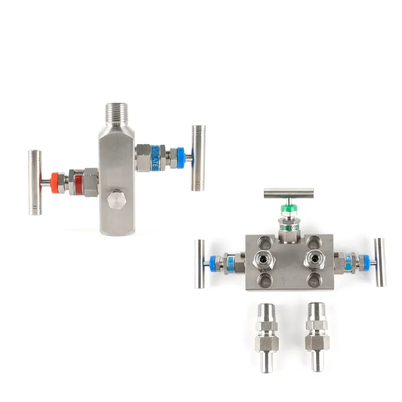
Manifold and Impulse Lines
A DP transmitter for orifice plate flow usually needs a manifold and impulse lines. The manifold helps with isolation, equalization, and maintenance.
Common accessories include:
- 3-valve or 5-valve manifold
- Impulse line fittings
- Isolation valves
- Vent or drain valves
- Mounting bracket
- Condensate pots for steam, if required
Incorrect impulse line installation is one of the most common causes of poor DP flow measurement.
Conclusion
A differential pressure transmitter for orifice plate flow measurement should be selected together with the orifice plate calculation, fluid condition, line pressure, DP range, square-root signal handling, manifold, and impulse line installation.
SIY Electric can help check DP transmitter selection for orifice plate flow applications in liquid, gas, and steam service.