Connecting a pressure transmitter to PLC requires matching the transmitter output, PLC input type, power supply, wiring method, and signal scaling. A pressure transmitter may be correctly selected, but if the PLC input is wrong or the signal is not scaled properly, the displayed pressure value will be incorrect.
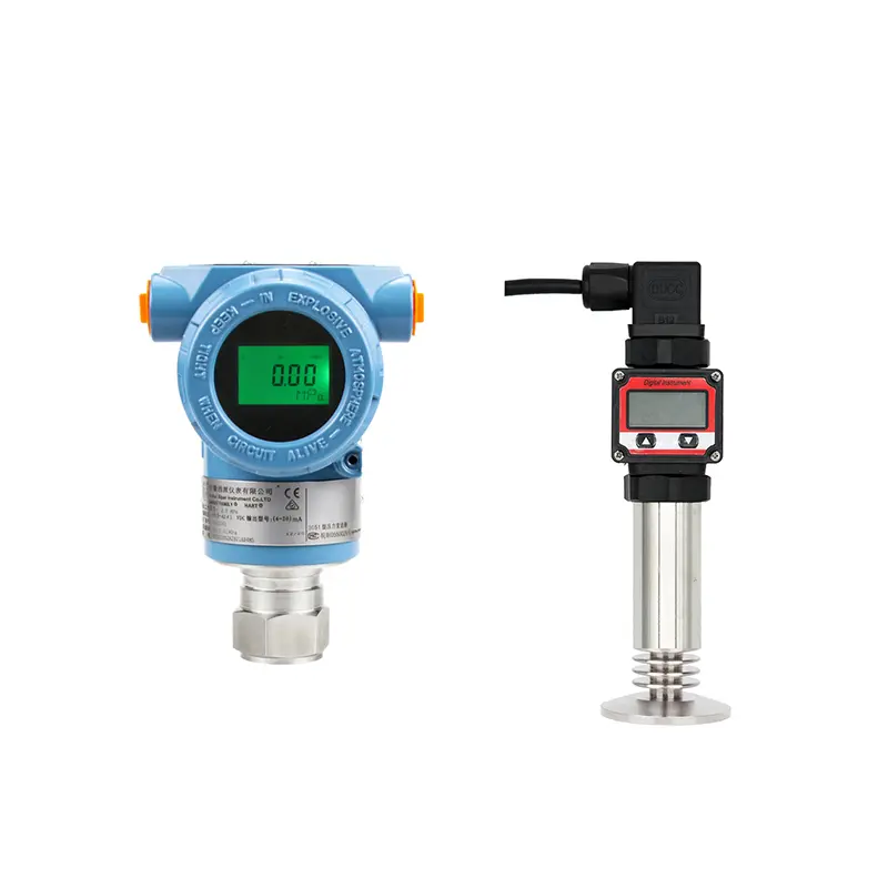
Most industrial pressure transmitters use 4–20 mA output. The PLC receives this current signal and converts it into a pressure value according to the transmitter range.
Confirm the Output Signal First
Before wiring, confirm what signal the transmitter provides. Do not assume all pressure transmitters are the same. Some use 4–20 mA, some use 0–10 V, and some use RS485 or Modbus.
For standard industrial applications, 4–20 mA is common because it is stable and suitable for long-distance transmission. If the transmitter uses HART, the analog 4–20 mA signal can still be used by the PLC, while HART provides additional digital communication for configuration or diagnostics.
Match the PLC Input
The PLC input module must match the transmitter signal. A 4–20 mA transmitter should connect to an analog current input. If it is connected to a voltage input without proper conversion, the reading may be wrong or missing.
Before connection, check:
- Whether the PLC input supports 4–20 mA.
- Whether the input is active or passive.
- Whether external 24 VDC power is needed.
- Whether the transmitter is 2-wire, 3-wire, or 4-wire.
- Whether the input channel is correctly configured in PLC software.
This step is especially important when replacing an old transmitter or changing the PLC input card.
Scaling the Signal
Wiring only completes the electrical connection. The PLC must also scale the signal correctly. The lower pressure range should correspond to 4 mA, and the upper pressure range should correspond to 20 mA.
For example, if the transmitter range is 0–10 bar, the PLC should interpret 4 mA as 0 bar and 20 mA as 10 bar. If the transmitter range is changed but the PLC scaling is not updated, the displayed pressure will be wrong.
Common Problems After Connection
If the PLC shows no signal, check power supply, polarity, wiring continuity, and input channel configuration. If the PLC shows a fixed value, the loop may be open, overloaded, or incorrectly wired. If the reading jumps, check grounding, shielding, cable routing, and interference.
Many PLC connection problems are not caused by transmitter failure. They come from wiring, scaling, power supply, or signal input mismatch.
Conclusion
To connect a pressure transmitter to PLC correctly, buyers should confirm output signal, PLC input type, wiring method, power supply, polarity, load resistance, and scaling range. A correct connection should provide a stable 4–20 mA signal that the PLC can convert into the real pressure value.
SIY Electric can help match pressure transmitters with PLC input requirements for industrial automation and equipment control systems.