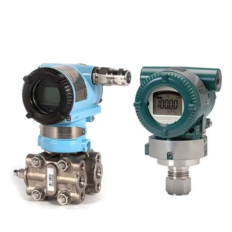
Calibrate a differential pressure transmitter by applying known pressure difference, checking output, and adjusting zero or span according to the required range. Differential pressure calibration is more sensitive than single-point pressure transmitter calibration because the transmitter has both high-pressure and low-pressure sides.
DP transmitters are used for flow, level, filter monitoring, and pressure difference measurement. If calibration is wrong, the entire flow, level, or filter signal may be wrong.
Before Calibration
Before calibration, confirm the required DP range, output signal, pressure unit, and whether square-root output is used. The transmitter should also be isolated safely from the process.
For field calibration, the manifold and impulse lines must be handled carefully. Trapped liquid, gas, or unequal pressure on the high and low sides can cause false readings.
The most important preparation items are:
- Confirm the DP range.
- Confirm high-pressure and low-pressure sides.
- Isolate the transmitter safely.
- Equalize both sides before zero check.
- Use a suitable pressure source and reference device.
- Check the 4–20 mA output or digital reading.
Do not adjust the transmitter before confirming that the test setup is correct.
Zero Calibration
For zero calibration, both sides of the DP transmitter should see the same pressure. This creates zero differential pressure. The output should normally correspond to the lower range value, such as 4 mA for a 4–20 mA transmitter.
If the zero output is shifted, zero adjustment may be needed. However, zero should not be adjusted if there is trapped pressure, blocked impulse line, wrong valve position, or unstable process condition.
Span Calibration
Span calibration checks whether the transmitter output matches the applied differential pressure at the upper range value. A known pressure difference is applied to the high-pressure side while the low-pressure side is referenced correctly.
The output should match the expected value. For a 4–20 mA transmitter, the upper range value normally corresponds to 20 mA.
For flow measurement, also check whether square-root extraction is done in the transmitter, PLC, DCS, or flow computer. Double square-root configuration can cause serious errors.
Common Calibration Mistakes
Most DP calibration problems come from the test setup, not the transmitter itself.
Common mistakes include:
- High and low sides connected incorrectly.
- Zero adjusted while DP still exists.
- Impulse lines not vented or drained.
- Manifold valves operated in the wrong order.
- Square-root output not confirmed.
- Calibration range does not match PLC scaling.
A careful calibration procedure should check both the transmitter and the whole measurement loop.
Conclusion
To calibrate a differential pressure transmitter correctly, confirm the range, isolate the transmitter safely, equalize both sides for zero, apply known differential pressure for span, and verify output scaling. For DP flow or level applications, installation and signal configuration must also be checked.
SIY Electric can support differential pressure transmitter selection, manifold matching, and troubleshooting for calibration, zero drift, and unstable DP readings.