Installing a differential pressure transmitter correctly requires proper high and low pressure connections, impulse line layout, manifold operation, mounting position, and venting or draining. A DP transmitter may be selected correctly, but poor installation can still cause unstable readings, zero drift, slow response, or wrong measurement.
Differential pressure transmitters are used for flow, level, filter monitoring, and pressure drop measurement. Each application has its own installation details, but the basic principle is the same: the transmitter must receive the true pressure difference between two points.
High Side and Low Side Must Be Correct
The high-pressure side and low-pressure side should match the process design. If they are reversed, the transmitter may show negative differential pressure or a confusing output.
For filter monitoring, the high side is normally connected before the filter and the low side after the filter. For flow measurement with an orifice plate, the tapping points should follow the primary element design. For level applications, the connection depends on open tank, closed tank, wet leg, or remote seal arrangement.
Impulse Line Layout
Impulse lines should transmit pressure without trapping unwanted gas, liquid, dirt, or condensate. Their layout depends on whether the service is gas, liquid, or steam.
For liquid service, trapped gas should be avoided. For gas service, trapped liquid should be avoided. For steam service, condensate legs and temperature protection must be handled correctly.
Poor impulse line layout is one of the most common reasons for bad DP readings. The problem may look like transmitter drift, but the real cause is often trapped air, trapped liquid, blockage, or wrong slope.
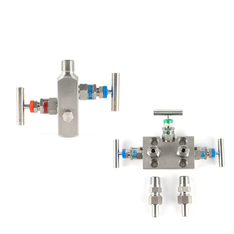
Manifold and Valve Operation
A DP transmitter usually uses a 3-valve or 5-valve manifold. The manifold helps with isolation, equalization, zero checking, venting, draining, and maintenance.
The manifold should be installed so operators can safely isolate the transmitter, equalize both sides, and return it to normal service without creating overpressure or false readings. Wrong valve operation can damage the transmitter or create an incorrect zero.
Mounting and Accessibility
The transmitter should be mounted securely and in a position that supports stable measurement and maintenance. It should not hang only from weak impulse lines. A mounting bracket is often needed, especially for industrial DP transmitters.
The installation should also allow access to the manifold, vent valves, drain valves, wiring terminals, and display. If the transmitter is difficult to reach, maintenance problems will become more frequent.
When Remote Seals Are Better
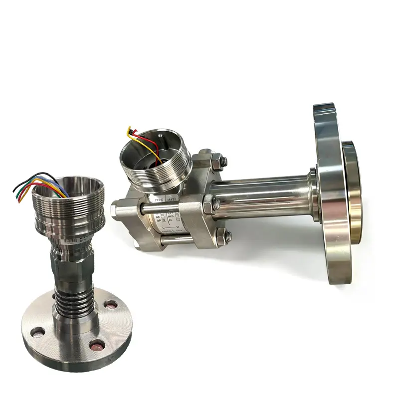
Impulse lines are not suitable for every medium. If the medium is corrosive, viscous, dirty, crystallizing, or easy to freeze, remote diaphragm seals may be better. They can reduce blockage and corrosion risk, but capillary length, fill fluid, and installation height must be considered.
Conclusion
To install a differential pressure transmitter correctly, buyers and technicians should check high and low side connection, impulse line slope, manifold arrangement, mounting position, venting, draining, wiring, and whether remote seals are needed.
SIY Electric can help supply differential pressure transmitters with manifolds, brackets, fittings, and remote seal configurations for flow, level, and filter applications.