A pressure transmitter hook-up drawing should show how the transmitter is mechanically connected to the process, valves, fittings, accessories, and mounting support. It is different from a wiring diagram. A wiring diagram explains electrical connection. A hook-up drawing explains field installation.
In industrial projects, hook-up drawings help engineers, installers, and buyers understand what accessories are needed before installation. They also reduce missing parts, wrong connections, and site delays.
What a Hook-Up Drawing Is Used For
A hook-up drawing shows the complete installation arrangement around the pressure transmitter. It may include process tapping point, isolation valve, manifold, adapter, impulse line, mounting bracket, drain valve, vent valve, cable gland, and other accessories.
For a simple threaded pressure transmitter, the hook-up may be very simple. For differential pressure, steam, diaphragm seal, or high-temperature applications, the hook-up becomes more important.
The drawing helps answer practical questions:
Can the transmitter be isolated? Can it be calibrated? Can it be removed safely? Does the process connection match? Are the required accessories included?
Key Items to Include
A useful hook-up drawing should include the items that affect installation, maintenance, and safety.
Important items include:
- Process connection
Thread, flange, adapter, or seal connection should be clear. - Isolation valve
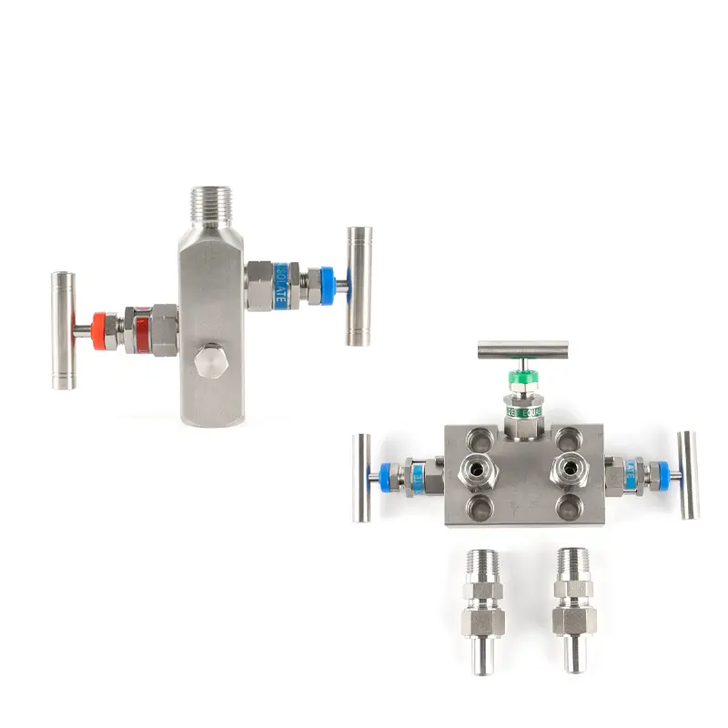
This allows the transmitter to be removed or maintained safely. - Manifold
Required for many differential pressure transmitter installations. - Vent or drain valve
Needed depending on gas, liquid, steam, or DP application. - Mounting bracket
Used when the transmitter should not be supported only by piping. - Accessories
Siphon tube, cooling element, snubber, impulse line, or fittings may be needed. - Material and rating
Valves, fittings, and adapters should match pressure, temperature, and medium.
Why Buyers Should Care
Many transmitter orders are delayed not because the transmitter is wrong, but because accessories are missing. The buyer may receive the transmitter but cannot install it because the valve, adapter, manifold, flange, or bracket was not ordered.
A hook-up drawing helps clarify the full installation package before shipment. This is especially useful for replacement projects, EPC projects, and export orders.
Difference From Wiring Diagram
A pressure transmitter wiring diagram shows electrical terminals, power supply, signal output, and PLC input. A hook-up drawing shows the mechanical installation around the transmitter.
Both may be needed. The wiring diagram helps the electrician. The hook-up drawing helps the instrument installer and piping team.
Conclusion
A pressure transmitter hook-up drawing should include process connection, valves, adapters, manifold, vent or drain points, mounting bracket, accessories, material, and pressure rating. It helps prevent installation delays and missing accessory problems.
SIY Electric can help buyers match pressure transmitters with valves, manifolds, fittings, brackets, cooling accessories, and hook-up requirements for project installation.