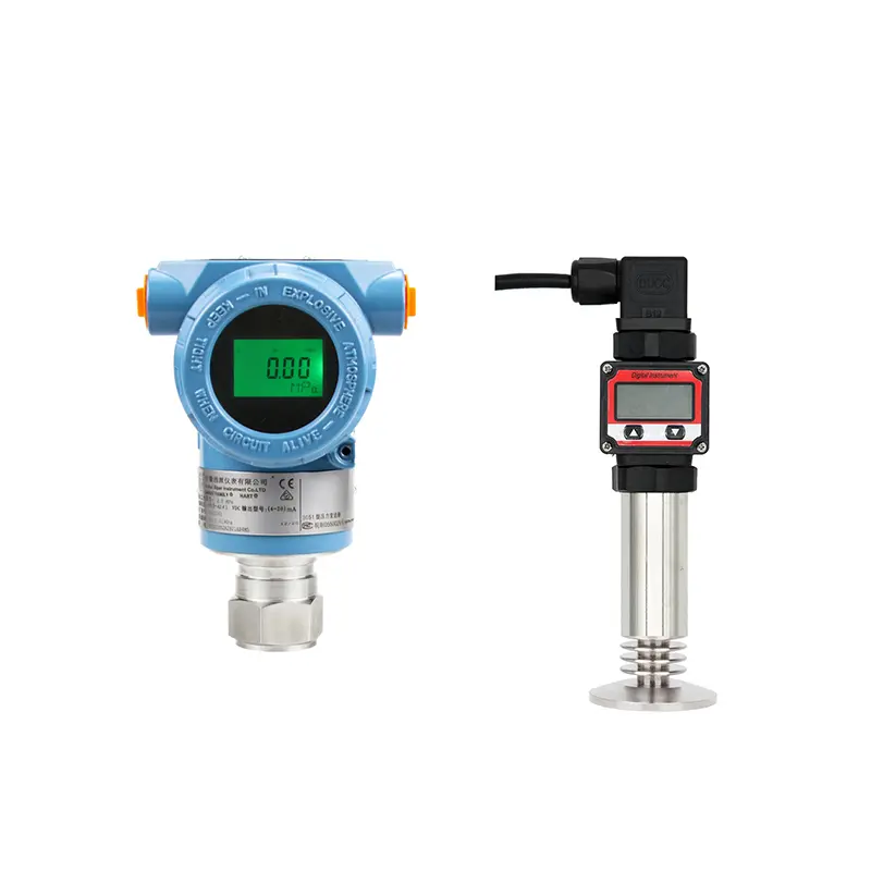
Test a pressure transmitter before installation by checking appearance, wiring, power supply, output signal, pressure response, and configuration. This simple step can prevent many site problems, especially for replacement orders, project shipments, or instruments stored for a long time.
Pre-installation testing does not need to replace full laboratory calibration. Its purpose is to confirm that the transmitter is the correct model and responds normally before it is mounted on the process.
Check the Basic Information First
Before applying pressure, compare the transmitter with the order requirement. A transmitter may work normally but still be wrong for the application if the range, output, or process connection does not match.
Check these items first:
- Model number
- Measuring range
- Pressure type
- Output signal
- Power supply
- Process connection
- Diaphragm or wetted material
- Approval or marking, if required
This is especially important for replacement jobs where the new transmitter must match an old model.
Check Wiring and Output
Connect the transmitter according to its wiring type. For a 2-wire 4–20 mA transmitter, make sure the power supply, transmitter, and meter or input device form a complete current loop.
After power is applied, check whether the output is reasonable. At zero pressure or atmospheric condition, the signal should match the expected lower range condition, depending on pressure type and configuration.
If there is no output, check power supply, polarity, loop connection, and input type before assuming the transmitter is faulty.
Apply Pressure Step by Step
If suitable test equipment is available, apply pressure gradually and observe the output. For a 4–20 mA transmitter, the output should change smoothly as pressure increases.
A simple pre-installation check can include:
- Zero point check
- Mid-point response check
- Full-scale response check, if safe and possible
- Output stability check
- Display reading check, if the transmitter has a display
The goal is to confirm that the transmitter responds normally and the output is not stuck, jumping, or reversed.
Check Configuration
For smart transmitters, confirm range, unit, damping, output mode, and communication settings. If the transmitter is used for DP flow, confirm whether square-root output is required and where the square-root calculation will be done.
For replacement applications, make sure the transmitter range and PLC scaling match. A working transmitter can still show wrong process values if scaling is not consistent.
Conclusion
To test a pressure transmitter before installation, check the model, range, output, wiring, power supply, pressure response, and configuration. This helps avoid installing the wrong product or troubleshooting wiring and scaling problems after the instrument is already on site.
SIY Electric can help buyers check pressure transmitter configurations before shipment or replacement installation.